Tuesday, August 26, 2008


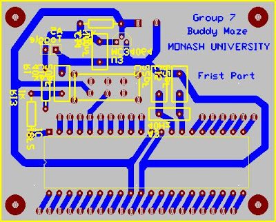
Today is the day to finish my PCB. We have finalized our schematic design therefore I can finish the whole PCB.
The PCB will be a double decker PCB with the top part consist of PIC and the circuit. The bottom part will consist of 2 voltage regulator circuit, 2 switches, motor driver and a pair of motors circuit. We are using 2 battery types that consist of a 9V square DC battery and 5 rechargeable batteries of 1.2V. The 9 Volts battery will be used to drive the electronic circuit and the other for the motors.

For the chases, we are using a plate of aluminum with a thickness of 2 mm. We are using 3 SHARP IR sensors. These sensors will be placed at front, right and left. At the front of the chases will be placed 2 batteries holder with 5 batteries attached to it. Two motors will be attached at the bottom of the chases. A 9 Volts battery will be placed at the back of the bottom chases.

With all of that, the physical body of the robot is finished and ready to be built. The other problem that is needed to be done is for the programming. Right now we are still learning how to use the compiler and we hope that we will be able to finish the project on time.
Friday, August 22, 2008

First PCB design


This week we were getting part of the component. We also have finalized our base body of the robot; therefore it was the time to build the PCB. I am the person in charge of building it. At first when I am building the PCB, I am thinking of using only one decker because the entire component can fit. But after some consideration about the compactness of the PCB, we are changing our mind.
At this time we are building the microprocessor component separate from other circuit. It will become a double decker PCB with top part of PIC since we may need to plug in and out frequently. The other part of the circuit will be built on the bottom PCB. This PCB couldn’t be finalized yet since we are still not sure about the other component we will get. We are planning to use the SHARP IR sensor that will come with its own circuit.It is better to design the PCB after all of the components have been finalized therefore the changes of the PCB structure does not need to be done so frequently.

Sunday, August 17, 2008

Body Design

This is the leatest robot body design. This body use 1mm thin aluminum that can be fitted with 2 DC motors and multiple layer of PCB above.
Designed by Handy with some idea from Edy SP

Circuit Diagram


This is the leatest circuit diagram that use PIC18F452 and 2 DC motors

Second Blog

This is the 2nd block I’ve made. Until now, there wasn’t much we can do since the components haven’t arrived. For the past two weeks what all of us have done was collecting information from internet, datasheet and books.

After the gathering of information, Handy said that he will do the body design part using solid edge and he left the rest work for two of us to do. I chose to do the PCB design using the Trax Maker and Budi was in charge in schematic circuit design. So I’ve to wait for Budi to finish his design first. But then I realized that I couldn’t do the design since I didn’t know exactly the size of each component and the component that we will get. Because of that I was ending up with doing nothing. What could do is only to help them with their work. I rechecked the work they have done and gave them a feedback. I also redesign the Schematic diagram that has been done by Budi to make my life easier later when I’ve to really design the circuit.

This Wednesday was the due of the lab report, so we were more concentrated in the report for. We again divided our job to finish the report. We did the report based on the job we have assigned early. I was doing the circuit modification part, Gantt chart, network diagram, part of responsibilities matrix, part of work breakdown structures and part of activities. As most of us were quite busy with the report, we hardly done some research about the robot. On the Wednesday after the report submission, we started to discuss about the robot again.

On the day of discussion, we’ve made big changes of our robot design. We changed our plan from using servo to DC motor due to the speed limitation of the servo. The microcontroller was also changed from PIC16F87 to PIC18F452. These changes made us redesign almost all part of the robot; from the body of the robot to the circuit diagram. Though a lot of changes need to be made, I feel a bit lucky that I haven’t started to do the PCB design first.

This Friday Joshua took us to buy the DC motor. But since the car couldn’t fit a lot of people, only one of us that have gone to bought the motor. We bought the DC motor with double gear box. The wheel can move independently one another. The next day, we built the gears and wheels. At that time, we encounter a very big problem. The gear we’ve bought was incorrect and couldn’t be used. We called the shop and the shopkeeper asked us to go back to the shop to get the missing components. Finally 3 of us: I, Handy and Hendry (other groups that bought the same motor with same faulty gears) went to the shop again to get the components. After went home, we built it again and test the motor, luckily this time the motors with the gears works. The next day Handy redesigned the body of the robot. We discuss about the changes of robot and finally came out with new design. Until now what we could do was this far since we don’t have any robot’s components yet. We hope to get all of the components fast since the due date of the competition is getting nearer.